Sunday, August 21, 2011

Dry fitting of longitudinals...


Vacuum bagging a foam floor.


I was fortunate to find a used carbon fiber mast from a J/90, light and strong.  It turns out to have quite a history.  It is from Eye-Eye which was previously Surfinn.  Ryan Finn completed the Single Handed TransPac in 2004 in Surfinn with a corrected time of 11:06:11:30.


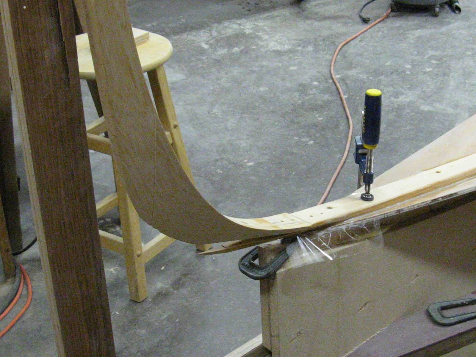
The longitudinals make up the fronts of the cockpit seats as well as the bunk fronts.  Here they are being dry-fitted against the hull and over the floors prior to gluing the puzzle joints.


The outboard motor goes through a well a few feet forward of the transom.  The cut out in the hull forms the bottom of a plug which goes into the motor well when the motor is stowed in a cockpit locker


There are watertight voids at both ends of the boat which can be accessed via 10" inspection plates.  The plates screw into their frames with a watertight o-ring seal.  Doubler  rings reinforce the bulkheads.

Saturday, July 2, 2011

Floors 2...


This is the grounding floor, designed to take the load from the keel when I run aground (not if, but when).  It is laminated spruce and will be reinforced with 4 layers of 300 g fiberglass cloth.  The side pieces are vertical grain fir.


The foam floor in the foreground has been reinforced with fiberglass and carbon cloth using a vacuum bag.

Thursday, June 9, 2011

Fillets, Foam Floors 1...

A fillet is necessary on both sides of the bulkheads where they intersect the hull strakes and everywhere else where plywood panels meet.  I am using a mix of fillers recommended by Russell Brown which results in a medium hard fillet that is still sandable.  The area of the fillet is primed with straight epoxy + hardener, then fillers are added to the remaining epoxy mix until a peanut butter consistency is reached.  The mix is applied to the primed joint and smoothed with a stick cut to the proper radius.


Now I am working aft of the keel trunk installing the floors.  There are three floors that are built up from layers of foam and a spruce floor that will be immediately aft of the trunk.


Each layer of foam was cut using a full-sized pattern furnished by Bieker Boats.  Six layers of 1/2" foam are glued together.


This floor has been shaped to fit and is ready to be glued to the hull strakes.  The 1" PVC limber on the center line will allow spilled water to flow to a collection area lower in the boat.


Floors A and B have been glued and fillets have been started.  Floor C is being glued, held down by lead bars.


The three foam floors are almost ready for reinforcement.  They will each get 8 layers of 2" wide carbon tape interspersed with 4 layers of 300g cloth.  The two floors in the foreground will be extended up after #3 and #4 hull strakes have been installed.

Wednesday, March 9, 2011

Hull Stringers and #2 Hull Strakes...

Composite stringers will be used to add stiffness to the hull and deck.  A groove is cut in the 7/8 inch square spruce stringers to accept a 1/8 inch by 1/2 inch carbon fiber rod.  The carbon strip forms a flange on the stringer which allows the stringer to have a relatively small section but provide a lot of stiffness to the panel.  A wood only stiffener with the same stiffness would be about 1 1/2 times as wide and deep.  Here a carbon rod is being glued into a spruce stringer.


The # 2 strakes have a bit of curvature up forward to conform to the shape defined by the bulkheads.  Kerfs cut in the forward section of these strakes make it easier to bend them.  The kerfs are cut with a Skil saw using a batten as a guide.


Here are the # 2 strake sections ready to be glued together.  Fiberglass cloth will be applied to both sides except on the inside of the forward section.  After the final shape is attained the kerfs will be filled with thickened epoxy and covered with fiberglass cloth.


Moving the completed panels from the table to the jig is a multi-person job.  The panels are floppy but strong.  Grant and Russ gave me a hand.

Looking aft, all these strakes will assume quite a different shape with the aft bulkheads and transom in place.

Starting to wire the #1 and #2 strakes together.  The Spanish windlass helps to pull the strake against the bulkhead.  One of the carbon fiber/spruce stringers loosely in place.


Minte is helping with the tie wires.


Forward Bulkheads...

The bulkheads are covered with a lighter weight fiberglass cloth than the hull strakes.  Here are the forward bulkheads and some other panels laid out on the table to be fiberglassed.  Both sides will be skinned and sanded before adding to the boat structure.


Here is the forward most bulkhead being positioned in the hull.


A view looking forward at the first three bulkheads with lazer alignment.  The bulkheads are attached to the hull strakes with #18 wire ties.


Looking aft.


The forward bulkhead has been glued to the hull strakes with thickened epoxy.  The size of the fillet will eventually be increased to a radius of 15 - 20 mm.


Wednesday, February 16, 2011

Attaching The Stem...

Here is the forward end of the keelson, ready for the stem.


 The stem is in position before gluing.


Clamps and temporary screws hold the assembly in position while the glue cures.  Barely visible is a lazer alignment line.


Here is a view of the forward end.


The completed assembly.

Wednesday, February 9, 2011

The Keelson...

The keelson was shaped from a 30mm by 50mm piece of spruce about 11 feet long.  It extends forward from the forward side of the keel trunk and attaches to the stem.  Eric created a drawing with full-sized sections every 500mm along the length of the keelson.  I glued the paper sections to thin plywood that I then cut into templates or patterns for each station along the keelson.  I shaped the keelson with a plane using the patterns as guides and blending between stations.  The bottom of the keelson forms a "V" which is flatter near the keel trunk and becomes sharper towards the bow.  Here is the keelson on the bench with the patterns at each station.


Screws hold the keelson in place while the thickened epoxy cures.  They were coated with a vegetable cooking spray so that they can be removed.